| |
| |
|
|
Building Name | |
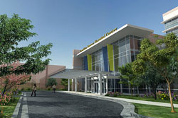
Franklin Square Hospital Center Patient Tower and Emergency Department Addition |
Location | |
9000 Franklin Square Drive ... Baltimore, MD 21237 |
Building Occupant Name | |
MedStar Health Facilities |
Function | |
Medical |
Size | |
356,000 square feet |
Number of Stories | |
7 stories |
Dates of Construction | |
Fall 2007 - Summer 2010 |
Overall Project Cost | |
$175 million |
Project Delivery Method | |
Design - Bid - Build |
|
| |
|
Owner | |
|
Project Manager | |
|
Architect | |
|
MEP Engineer | |
|
Structural Engineer | |
|
Civil Engineer | |
|
|
|
This building will provide healthcare needs to the people of the Baltimore area as well as additional visiting patients. Medical institutions are shaped for function rather then aesthetics. The rigid geometric shape of the hospital allows for a new adult emergency, pediatric emergency and fast track departments on the first level with a nurse’s station in the center of each. The new patient tower allows for 291 private patient rooms each with a window, private bath and ample space for visitors. The entrance lobby is an inviting three-story open atrium space.
Building Code | |
IBC 2006 Edition with Baltimore County Amendments |
Fire Protection Code | |
NFPA 101, Life Safety Code 2006, International Fire Code 2006 Edition with Baltimore County Amendments |
Health Department Code | |
AIA Guidelines for Hospital and Health Care Facilities, 2006 |
Handicapped Requirements | |
ADAAG, American with Disabilities .. Act – Public Law 101-336 |
Electrical Code | |
NEC 2005 |
Mechanical Code | |
International Mechanical Code 2006 |
Plumbing Code | |
National Standard Plumbing Code 2003 with 2004 Supplement |
Energy Code | |
International Energy Code 2006 |
Zoning | |
Baltimore County Zoning Regulations |
Historical Requirements | |
None |
|
|
|
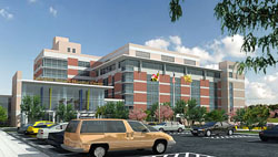
The exterior façade of the addition will resemble the façade of the existing hospital. Portland cement stucco, red face brick and precast concrete cladding units are assembled to create the matching façade. A curtain wall system composed of aluminum framing and argon filled PPG Solarban 80 insulating spandrel tempered glass is used throughout the first level and entryways. Roof construction will consist of two types of roofing. EP single-ply membrane roofing that includes a non-traffic-bearing sheet membrane system intended for weather exposure as primary roofing used on the new patient tower and entry canopies. The remaining rooftop area is covered by a modified bitumen roofing system. This system consists of two plies of type IV fiberglass felts installed in type III asphalt and coated in one ply of mineral surfaced, Class A fire rated, SBS/SIS modified cap sheet that solidly bonds to the underlying plies when heat is applied by torch, to insure a solid bond. |
|
|
Not LEED Certified but there is post-design consideration for certification. Patient care was a higher concern when designing this medical center therefore the importance of facility sustainability has been sacrificed at times. |
| |
|
The Franklin Square Hospital Center addition consists of the construction of a new seven story tower with walk-out emergency department ground floor, six floors of new patient rooms including one floor of ICU rooms, a penthouse floor, a roof designed for a future heliport, a new three story entry lobby with a new gift shop, a new meditation room, and a new admitting suite. There will be renovations to the materials management building and existing ICU to construct new corridor tie-ins. The central energy plant will receive new boilers, chillers, generators, electrical switchgear and cooling towers. Sitework includes the construction of the entrance plaza and installation of additional utilities. |
| |
|
Normal power to the hospital is supplied by the Baltimore Electric Utility Company. Two 13.2KV underground feeders enter the building at the northwest corner and terminate in a 15KV class switchgear rated at 1200A. Wiring size is #12AWG minimum for a typical 20A, 120V or 277V lighting or receptacle branch circuit with a maximum total length of 60 feet and 150 feet respectively.
The uninterrupted power system is 3 phase on-line solid state system rated at 180KVA/162KW. The input current is 260A with a power factor up to 0.98 lagging. The output voltage is208Y/120VAC 3 phase 5W.
Emergency power of 480Y/277V 3 phase 4W, to the hospital is supplied by three 480Y/277V, diesel engine generator sets of 2000KW capacity. The generator sets are mounted on a heavy duty steel base to maintain proper alignment between components and provide power within 10 seconds. The emergency power bus is rated at 10,000A at 480Y/277V. |
| |
|
Track lighting, linear/perimeter lighting, cold cathode lighting and custom fixtures are found through the entire building. All incandescent lamps will have a long life of 2500 hours and a voltage of 130V if available. Fluorescent T8 lamps contain a low amount of mercury, have a minimum life of 15,000 hours and have a CCT of 4100K. All fluorescent ballasts are electronic, “Class P” type, have a sound rating of “A” and have a high power factor of 0.95 or greater. Compact fluorescent twin-tube lamps are rated at an average life of 10,000. High intensity discharge lamps have a minimum of 20,000 hours of lamp life. Ultrasonic and infared occupancy sensors are supplied in rooms including the lobby along with many others. |
| |
|
Six new air handling units shall be installed in the penthouse of the patient tower along with the new heating hot water plant. The building will be served by variable air volume terminal units with hot water reheat and the return system will be a variable volume system with return air terminal units. |
| |
|
The building foundation sits on cassions with a shaft diameter ranging from 1’-6” to 5’-0”. Typical concrete column sizes are 22x22 and 21x21 with vertical bars 8#9 and 8#11 respectively. W-shape steel column size varies and sits on concrete pier footings. Composite and concrete beams are used throughout the addition. |
| |
|
The building is protected with an automatic sprinkler system along with an approved automatic fire alarm system throughout the new facility. Portable fire extinguishers, manual pull stations, magnetic door closers along with an annunciation system, using horns and strobes, are located throughout the building. Selected doors on staircases are equipped with hardware to prevent re-entry
Sprayed fireproofing is applied to all new structural steel and metal decking where indicated for UL assembly. In renovated areas, the fireproofing is patched where it has been removed. Fire partitions range as well as fire and smoke barriers are rated at one or two hours. |
| |
|
The building is serviced by four elevators of which two are for public use and two are strictly used as service elevators. All of the elevators are geared traction type and have a rated speed of 350 fpm. The public elevators provide access to all seven the patient tower floors and have a rated load of 3000 lbs. Service elevator #1 has a rated load of 7500 lbs and #2 has a rated load of 5000 lbs.
Two staircases connect the ground level through the seventh floor of the patient tower. These are located at the northeast and southeast ends of the tower. A centralized staircase located next to the main lobby connects the ground level to the roof. One other stair connects the exterior first floor level, next to the meditation garden, to the second floor. |
| |
|
VOIP, data and video communications originate at local area network switch equipment that is placed on vertical freestanding equipment racks. The CATV system requires RG-6 co-axial cables in each of the patient rooms, waiting areas and other locations throughout the facility. Category 6 cables are used for the hospital standard voice/data system. |
| |
|
|
|